Giving a 1960s Doorbell Chime a Second Life with Home Assistant
I didn't even know I had a doorbell chime.
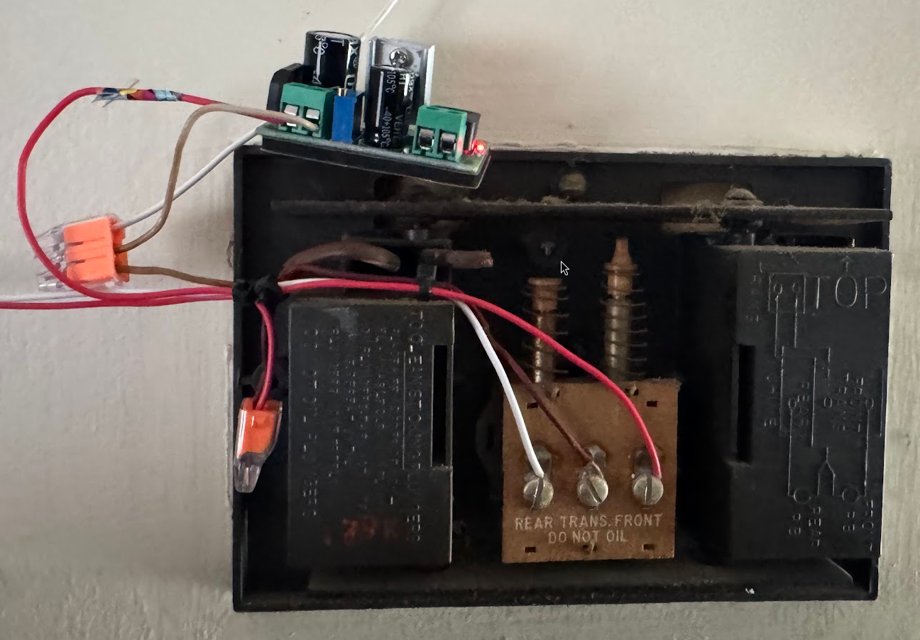
Tucked away in the hallway, mostly hidden behind the 75" TV we mounted shortly after moving in, sat a cream-colored plastic cover I'd walked past a thousand times without a second thought. It wasn't until I started mapping out my home automation setup that I pulled off the cover and found this:
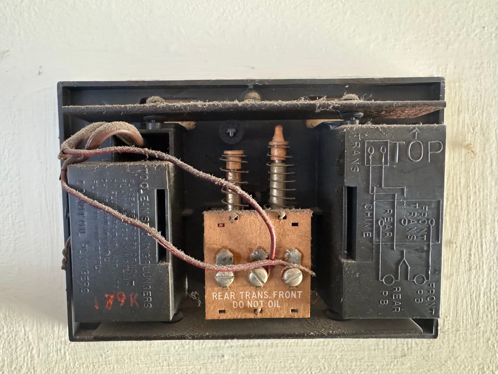
A vintage NuTone LA-12 mechanical chime — probably original to the house, which puts it somewhere in the 1960s. Two brass tone bars, two spring-loaded solenoid plungers, and a wiring diagram embossed right into the metal housing. The kind of overbuilt, repairable hardware they don't make anymore.
The catch? It was wired to a door we literally never use. A side entrance that's been blocked by furniture since we moved in. The chime worked perfectly — my daughter confirmed this by pressing the button while I stood there, startled by the sudden ding-dong from three feet away — but it had been silent for years.
That's when the idea hit me: what if I could trigger this thing from Home Assistant?
Understanding the Circuit
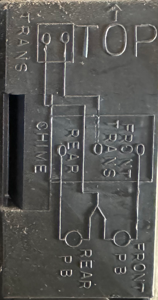
Before writing any code, I needed to understand what I was working with. Traditional doorbell wiring is elegantly simple:
A transformer (hidden somewhere in the house) steps 120VAC down to a safe 16-24VAC. One wire runs from the transformer to the chime's TRANS terminal. Another wire runs from the FRONT terminal out to the doorbell button, then back to the transformer. When you press the button, you complete the circuit, current flows through the solenoid, and the plunger strikes the tone bar.
My daughter and I did some reconnaissance with a multimeter. With the button unpressed: 0V across all terminals. With the button held down: ~18VAC between TRANS and FRONT. The circuit was only live when the button completed the return path.
But here's what made the project feasible: I found two cables entering the chime box, each with two wires. The "extra" wires from each cable were twisted together off to the side.
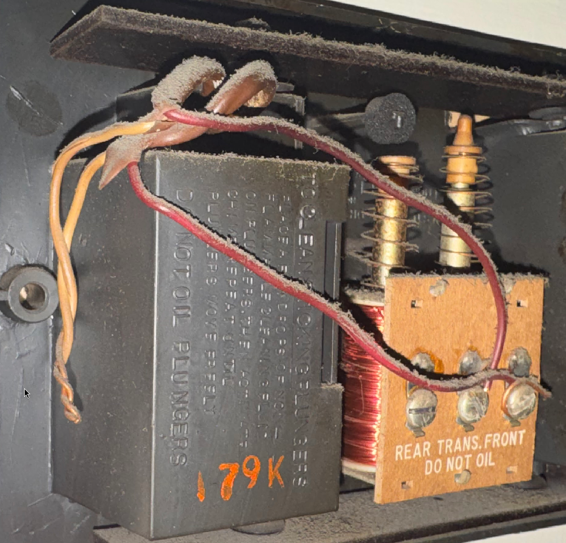
That splice is the neutral return path. When I measured from that twisted splice to the TRANS terminal, I got a constant 18VAC — even with the button unpressed. The transformer's power was right there, waiting to be tapped.
This meant I didn't need to hunt down the transformer, run new wires, or do anything complicated. Everything I needed was already in the chime box.
The Plan (Version 1: Overengineered)
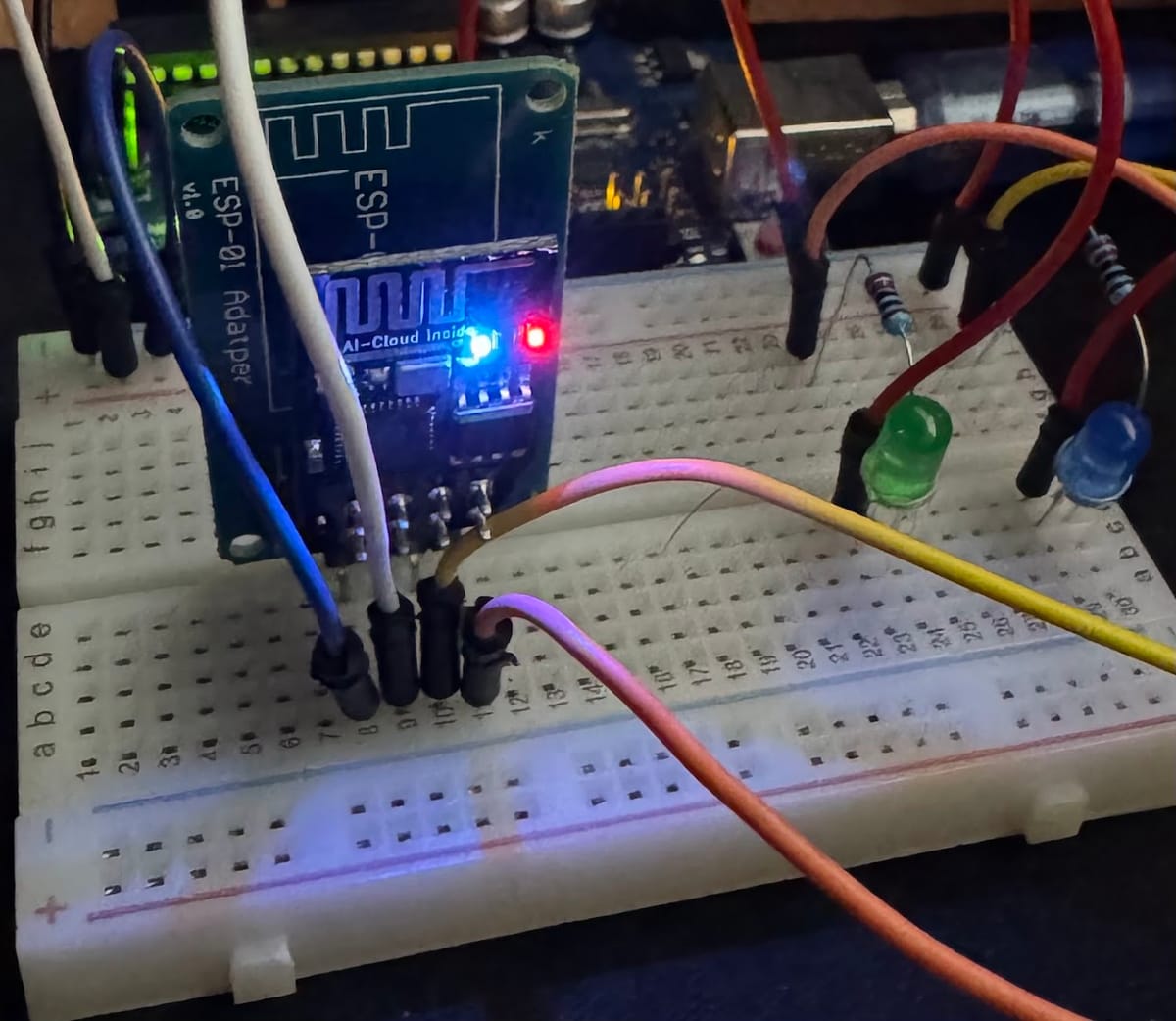
My first instinct was to use hardware I had on hand: an Arduino Uno and an ESP-01 module. The ESP-01 would handle WiFi and MQTT, the Arduino would run the logic and control the relays. Clean separation of concerns, right?
Here's what that architecture looked like:
Home Assistant → MQTT Broker → ESP-01 (WiFi) → Serial → Arduino Uno → Relays → ChimeI wrote the Arduino sketch, set up SoftwareSerial to communicate with the ESP-01, and started debugging. And debugging. And debugging.
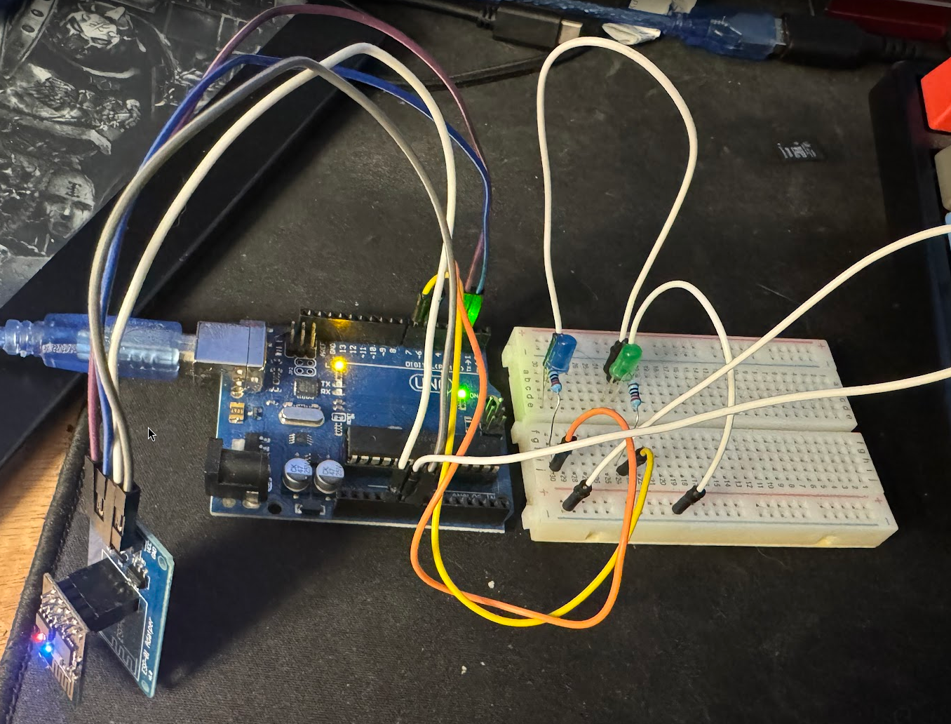
The Problems Started Immediately
Problem 1: SoftwareSerial buffer overflows. MQTT packets are bigger than you'd think, and SoftwareSerial's default 64-byte buffer couldn't keep up. I had to add this hack at the top of the sketch:
#define _SS_MAX_RX_BUFF 256Problem 2: The WiFiEsp library had a parsing bug. My ESP-01's firmware returned unquoted IP addresses, but the library expected quotes. I ended up patching the C++ source:
// File: Arduino/libraries/WiFiEsp/src/utility/EspDrv.cpp
// Around line 685, change from:
     espSerial->read();
     espSerial->read();
// To:
     espSerial->read();
Problem 3: MQTT connections kept dropping. Duplicate Client IDs caused the broker to kick the device off in an infinite loop. Silent subscription failures because I forgot authentication credentials. The Arduino would connect, subscribe, and then... nothing.
Problem 4: Brownouts. The ESP-01's WiFi radio pulls up to 300mA during transmit bursts. Powered through the Arduino's voltage regulator without decoupling capacitors, it would randomly reset.
I got it working, eventually. Here's the Arduino sketch in its final form:
// Increase SoftwareSerial RX buffer from 64 to 256 bytes
#define _SS_MAX_RX_BUFF 256

#include <WiFiEsp.h>
#include <WiFiEspClient.h>
#include <PubSubClient.h>
#include <SoftwareSerial.h>

const char ssid[] = "MyNetwork";
const char pass[] = "MyPassword";
const char* mqtt_server = "192.168.88.69";
const char* mqtt_topic = "home/chime/#";

const int RELAY_DING = 7;
const int RELAY_DONG = 6;
const unsigned long STRIKE_DURATION = 50;

SoftwareSerial EspSerial(2, 3);
WiFiEspClient espClient;
PubSubClient client(espClient);

// ... 150 more lines of connection handling,
// non-blocking relay timing, and aggressive polling
// to compensate for SoftwareSerial's limitations
It worked. It was also fragile, complex, and required two boards plus a rats nest of jumper wires. There had to be a better way.
The Pivot: What If We Just... Didn't?
The ESP-01 is a full microcontroller. It runs at 80MHz, has WiFi built in, and can be flashed with custom firmware. Why was I using it as a dumb serial bridge?
Enter ESPHome.
ESPHome is a system for configuring ESP8266/ESP32 devices using simple YAML files. It handles WiFi, MQTT, OTA updates, and Home Assistant integration out of the box. Flash it once, configure everything in YAML, and push updates over the air.
I wiped the ESP-01, flashed ESPHome, and had it connected to my MQTT broker in about ten minutes.
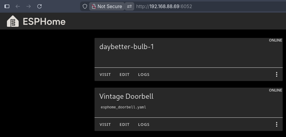
The entire Arduino — the SoftwareSerial hacks, the library patches, the connection management code — was now unnecessary. Gone.
The GPIO Problem
The ESP-01 is compact, which is great for fitting inside a chime housing. But it's limited — only a handful of GPIO pins are exposed, and the cheap blue adapter board I was using only broke out four pins: VCC, GND, TX, and RX.
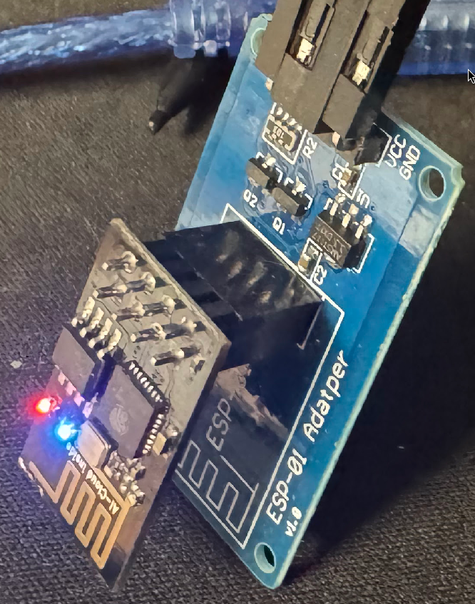
My original plan was to use GPIO0 and GPIO2, but those aren't accessible on the adapter without soldering to the chip or the board's underside. I don't currently own a soldering iron that can work at that scale.
Then I realized: TX and RX are GPIO pins. TX is GPIO1, RX is GPIO3. If I disable serial logging in ESPHome, those pins become available for general use.
logger:
  baud_rate: 0  # Frees TX/RX for GPIO use
Suddenly my "serial adapter" became a breakout board. No soldering required.
Power: The AC Problem
The chime box has 18VAC available from the transformer. My ESP and relays need 5VDC. Most buck converters expect DC input — feeding them AC would release the magic smoke.
I found an LM2596HV module. The key spec: "Input: AC 5V-30V or DC 5V-50V" — it has a bridge rectifier built in.
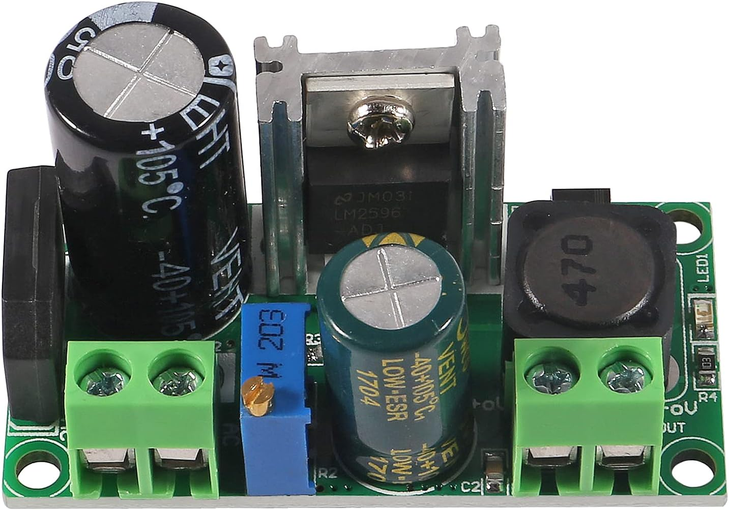
Wire the 18VAC in, adjust the trimpot to 5V output, and you've got clean DC power without any additional components.
The Final Build
Here's what went into the chime box:
- ESP-01 in its blue adapter board (provides 3.3V regulation)
- LM2596HV buck converter (18VAC → 5VDC)
- Two single-channel relay modules
- Twin wire ferrules for splitting the 5V power to multiple boards
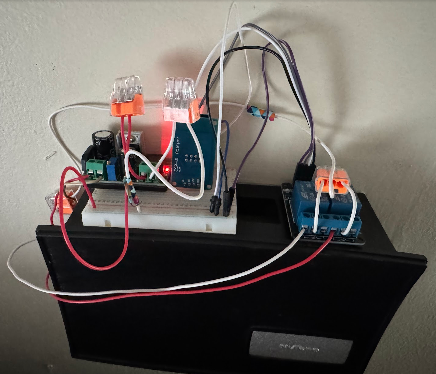
I had grand visions of fitting everything inside the chime housing — the original plan was to "Tetris" the components into the corners around the resonance chambers. Reader, it did not fit. Not even close.
The wiring:
TRANS (18VAC) ───────► Buck AC Input
Neutral splice ──────► Buck AC Input

Buck 5V Out ─────────► ESP VCC + Relay VCCs
Buck GND ────────────► ESP GND + Relay GNDs

ESP TX (GPIO1) ──────► Relay 1 IN (rear/ding)
ESP RX (GPIO3) ──────► Relay 2 IN (front/ding-dong)

Relay 1 NO ──────────► REAR terminal on chime
Relay 2 NO ──────────► FRONT terminal on chime
Relay 1 & 2 COM ─────► Neutral splice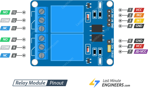
When the ESP triggers a relay, it bridges the chime terminal to neutral — exactly like pressing the physical doorbell button.
The final solution? The whole assembly just sits on top of the chime cover. Wires snake down through a gap to the terminals inside. It's not the invisible integration I'd imagined, but the chime lives behind a 75" TV anyway — aesthetics were never going to be a factor. Sometimes "good enough" is the right answer.
The ESPHome Configuration
The final YAML is remarkably simple compared to the Arduino sketch it replaced:
esphome:
  name: doorbell-chime
  friendly_name: Vintage Doorbell

esp8266:
  board: esp01_1m

logger:
  baud_rate: 0  # Free up TX/RX for GPIO

wifi:
  ssid: !secret wifi_ssid
  password: !secret wifi_password
  ap:
    ssid: "Doorbell-Fallback"

ota:
  platform: esphome

mqtt:
  broker: 192.168.88.69

  on_message:
    - topic: home/chime/ding
      then:
        - switch.turn_on: relay_ding
        - delay: !lambda |-
            int pulse = x.length() > 0 ? atoi(x.c_str()) : 100;
            if (pulse < 20) pulse = 20;
            if (pulse > 500) pulse = 500;
            return pulse;
        - switch.turn_off: relay_ding

    - topic: home/chime/ding_dong
      then:
        - switch.turn_on: relay_ding_dong
        - delay: !lambda |-
            int pulse = x.length() > 0 ? atoi(x.c_str()) : 100;
            if (pulse < 20) pulse = 20;
            if (pulse > 500) pulse = 500;
            return pulse;
        - switch.turn_off: relay_ding_dong

switch:
  - platform: gpio
    pin:
      number: GPIO1
      inverted: true  # Active LOW relay
    id: relay_ding
    name: "Ding Relay"
    restore_mode: ALWAYS_OFF

  - platform: gpio
    pin:
      number: GPIO3
      inverted: true
    id: relay_ding_dong
    name: "Ding Dong Relay"
    restore_mode: ALWAYS_OFF
The MQTT payload becomes the pulse duration in milliseconds. Send 150 to home/chime/ding_dong and the relay stays closed for 150ms. No payload defaults to 100ms. Bounds checking keeps it between 20-500ms so a stray value doesn't burn out a solenoid.
The Happy Accident
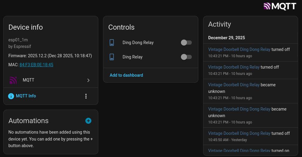
During testing, I noticed something odd: every time I pushed an OTA update, I'd hear a faint "ding" from the other room.
GPIO1 (TX) outputs serial data during the ESP8266's boot sequence — that's just what the boot ROM does. This brief burst of activity triggers the relay for a split second, causing the solenoid to give the tone bar a gentle tap.
I could probably fix this by mapping the less-important chime to that pin, or using a relay with a slower response time. But honestly? I kind of love it. It's audio confirmation that my firmware update completed. The house is telling me "I'm awake."
What It's For
The obvious use case is making this work as an actual doorbell again. I have an Amcrest video doorbell on the front door — when someone presses it, Home Assistant can trigger the vintage chime. There's something poetic about a 2024 IP camera activating a 1960s mechanical bell.
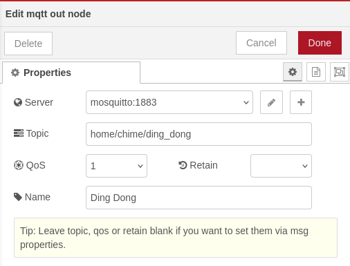
But the real value is in notifications. A smart home generates a lot of events, and not all of them deserve a phone notification. The dryer finishing? A single "ding." Someone at the front door? Full "ding-dong." A package delivered? Maybe a quick triplet pattern.
script:
  - id: triplet_ding
    then:
      - switch.turn_on: relay_ding
      - delay: 80ms
      - switch.turn_off: relay_ding
      - delay: 120ms
      - switch.turn_on: relay_ding
      - delay: 80ms
      - switch.turn_off: relay_ding
      - delay: 120ms
      - switch.turn_on: relay_ding
      - delay: 80ms
      - switch.turn_off: relay_ding
The chime becomes a physical notification system with semantic meaning. High priority, low priority, different patterns for different events. No screen required.

Lessons Learned
1. Reconnaissance before engineering. Ten minutes with a multimeter saved hours of wondering how to get power to the chime box. The answer was already there.
2. Simpler is usually better. The Arduino bridge architecture was clever. It was also fragile, complex, and unnecessary. The ESP-01 could do everything on its own.
3. Embrace the constraints. Limited GPIO forced me to think creatively about the TX/RX pins. The "limitation" of the adapter board became a feature.
4. OTA updates are non-negotiable. Imagine tuning that pulse duration — 50ms, 75ms, 100ms, 125ms — by physically reflashing the chip each time. ESPHome's over-the-air updates made iteration painless.
5. Don't die on the "elegant installation" hill. I spent way too long trying to fit everything inside the housing. The chime is 90% obscured by a 75" TV — literally nobody will ever see it. Function over form.
6. Old hardware is good hardware. This chime has been in continuous operation for 60+ years. The solenoids still work perfectly. The tone bars still ring true. It'll probably outlast every smart device in my house — including the janky electronics stack perched on top of it.
Bill of Materials
| Item | Cost |
|---|---|
| ESP-01S | ~$3 |
| ESP-01 Blue Adapter | ~$2 |
| LM2596HV AC/DC Buck Converter | ~$4 |
| 5V Relay Modules (x2) | ~$4 |
| Ferrules, wire, misc | ~$5 |
| Total | ~$18 |
Plus, of course, a vintage mechanical doorbell chime. Check your walls — you might already have one.
Final Thoughts
There's something deeply satisfying about making old things work in new ways. This NuTone chime spent decades doing one job — announcing visitors at a door nobody uses. Now it's part of a larger system, ringing out when the laundry's done or a package arrives, its mechanical ding-dong cutting through the digital noise of notifications.
Making the house "speak" through physical objects like an old-school chime is peak home automation. Not everything needs to be a screen. Sometimes the best interface is a brass bar and a spring-loaded hammer, doing exactly what it was designed to do — just triggered by software instead of a button.
This build will last 20 years. Just like the chime itself.